Ignition Coil Wiring Diagram ~ 350 Chevy Msd Ignition Wiring Diagram Line Diagrams Software. When you use your finger or even follow the circuit together with your eyes, it is easy to mistrace the circuit. It contains both primary and secondary winding circuits. 12 volt ferguson tractor wiring diagram basic browse diagrams general. The simple fix for this is to reverse the two primary wire connections on the ignition coil. Ignition coils of this type are usually a little larger than a soda can and are heavy.
Wiring diagram ws= white sw = black ro = red br = brown gn = green bl = blue gr = grey li = lilac ge = yellow ignition/starter switch, main fuse or = orange rs = pink audi a4 no. Connect the voltmeter red lead to the positive (+) terminal of the coil and the black lead to a good engine ground. 74 vw beetle ignition coil wiring diagram 1941 ford tractor audi a3 yenpancane jeanjaures37 fr. Ford ignition coil wiring diagram wiring diagram is a simplified enjoyable pictorial representation of an electrical circuitit shows the components of the circuit as simplified shapes and the gift and signal friends amid the devices. (do not disconnect wires from ignition coil).
Gm Coil Wiring Diagram Data Wiring Diagrams Supply from i.pinimg.com (do not disconnect wires from ignition coil). March 12, 2019 by larry a. It really is meant to aid all of the average consumer in building a correct system. 2,3 and 4 wire coil versions are different in control & monitoring strategies. The typical automotive ignition system prior to 1974 consisted of a coil and ballast resistor, with breaker points to interrupt the current flow when a spark was needed. In the years when engines were a lot easier to work with a ballast resistor was used in order to prolong the life of the coil. It shows the elements of the circuit as streamlined shapes, as well as the power and also signal links in between the tools. Primary current is an available test on all types:
March 12, 2019 by larry a.
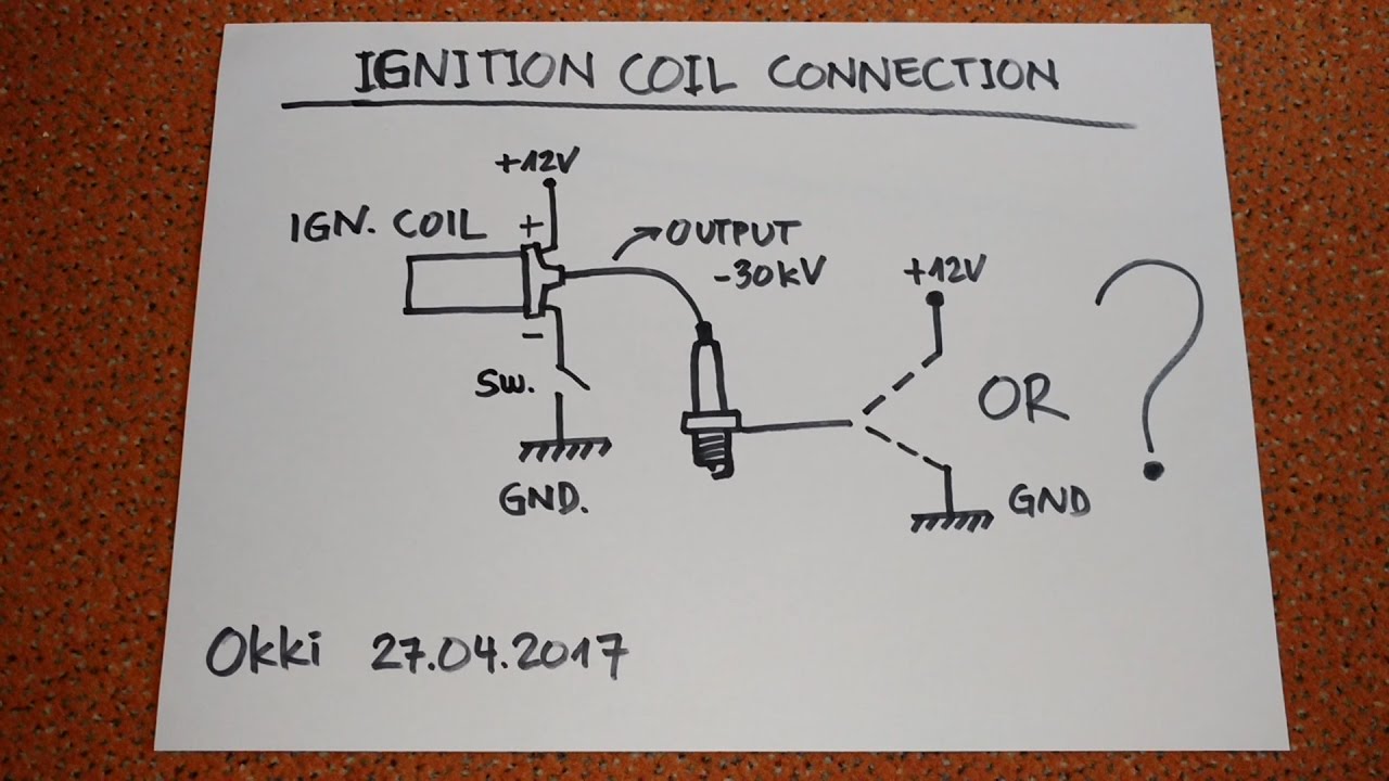
Connect the voltmeter red lead to the positive (+) terminal of the coil and the black lead to a good engine ground. Wiring diagram arrives with a number of easy to adhere to wiring diagram instructions. Accuspark wiring diagrams basic ignition system 5 4 8 primary coil diagram data 1929 a 6v to 12v terex switch ford tractor way 861 12 volt full systems short course model boat building standards 1962 chevy l6 relay an electrical circuit duraspark how wire motorcycle help you understand converting one alternator ferguson. Wellborn variety of mercruiser ignition wiring diagram. This applies to all old cub cadet ford jacobsen john deere wheel horse case and. Volkswagen coil wiring diagram vw bug index ford 12v data 1966 wire full chrysler alternator blog how to replace an ignition on beetle 74 honda 1969 harness points distributor fuse 19 ignitor 2 site bluebird a3re of pack 96 lexus es300 delco cd player dyna coils for 1993 dodge caravan box 1960 1980. Battery ignition using external coil. This wire must be insulated so that the voltage does not jump from loop to loop, shorting it out. Place ignition switch in the off position. They usually required only three wires: Put the other end of the test light on the positive terminal of the coil. Once you have voltage, crank the engine and the voltage should stay present. Because the output spark is very much higher voltage (20,000v) than the car battery (12v), it doesn't care if the battery polarity is helping or hindering by a meager 12 to 14 volts in battery potential.
The coil primary winding contains 100 to 150 turns of heavy copper wire. Otherwise, the structure won't function as it ought to be. These coils had very simple wiring. Connect the voltmeter red lead to the positive (+) terminal of the coil and the black lead to a good engine ground. Each part ought to be set and connected with different parts in specific manner.
Diagram Subaru Coil Pack Wiring Diagram Full Version Hd Quality Wiring Diagram Aidiagram Nuovogiangurgolo It from www.dsmtuners.com If you search the below document for the term coil driver you will find several sections of the instructions with information regarding this component. March 12, 2019 by larry a. Because the output spark is very much higher voltage (20,000v) than the car battery (12v), it doesn't care if the battery polarity is helping or hindering by a meager 12 to 14 volts in battery potential. The ignition coil is nothing more that an electrical transformer. If the light is still off, check for a bad connection between the coil and the key switch. It really is meant to aid all of the average consumer in building a correct system. How to test the gm distributor mounted ignition module. Primary current is an available test on all types:
Cylinder to cylinder variations are valuable.
74 vw beetle ignition coil wiring diagram 1941 ford tractor audi a3 yenpancane jeanjaures37 fr. The ignition coil is nothing more that an electrical transformer. If the test light is not lit, verify you have a good ground. Wiring diagram for ignition coil more information find this pin and more on 63 f100 wiring by ben platt. This tutorial will help you test the ignition coil, ignition module, and the crankshaft position sensor (pickup coil): The coils which are the basis for ignition coils and alternators have very specific electronic. How to properly connect this type of coil to your engine. Check wiring between ecu and ignition coil with ignitor, and then try another ecm. The wired differences matt dixon southern illinois university carbondale,. In the years when engines were a lot easier to work with a ballast resistor was used in order to prolong the life of the coil. If you search the below document for the term coil driver you will find several sections of the instructions with information regarding this component. The purpose of the ignition system is to create a spark that will ignite the fuel air mixture in the cylinder of an engine. March 12, 2019 by larry a.
Print the cabling diagram off plus use highlighters to be able to trace the circuit. 12 volt ferguson tractor wiring diagram basic browse diagrams general. The coils which are the basis for ignition coils and alternators have very specific electronic. Put the other end of the test light on the positive terminal of the coil. No ok connector replace sensor.
Ignition Coil Circuit Confusion Youtube from i.ytimg.com March 12, 2019 by larry a. Sometimes substituted for a failed magneto coil ignition syst. Wiring diagram for ignition system ignition system wiring diagram throughout ignition coil wiring diagram, image size 1146 x 344 px, and to view image details please click the image. Once you have voltage, crank the engine and the voltage should stay present. Connect the voltmeter red lead to the positive (+) terminal of the coil and the black lead to a good engine ground. Variety of chevy 350 ignition coil wiring diagram. 12 volt ferguson tractor wiring diagram basic browse diagrams general. Primary current is an available test on all types:
The typical automotive ignition system prior to 1974 consisted of a coil and ballast resistor, with breaker points to interrupt the current flow when a spark was needed.
When you use your finger or even follow the circuit together with your eyes, it is easy to mistrace the circuit. Wiring diagram ws= white sw = black ro = red br = brown gn = green bl = blue gr = grey li = lilac ge = yellow ignition/starter switch, main fuse or = orange rs = pink audi a4 no. This simple system is easy for even the novice mechanic to wire. A wiring diagram is a streamlined standard photographic representation of an electric circuit. The simple fix for this is to reverse the two primary wire connections on the ignition coil. The coils which are the basis for ignition coils and alternators have very specific electronic. (do not disconnect wires from ignition coil). Primary current is an available test on all types: The coil primary winding contains 100 to 150 turns of heavy copper wire. The purpose of the ignition system is to create a spark that will ignite the fuel air mixture in the cylinder of an engine. No ok connector replace sensor. Each part ought to be set and connected with different parts in specific manner. These guidelines will probably be easy to comprehend and use.